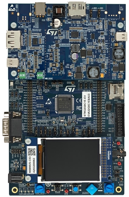
STM32G0C1E-EV

量産中

Evaluation board with STM32G0C1VE MCU

データブリーフのダウンロード

製品概要

概要

The STM32G0C1E-EV Evaluation board is a high-end development platform for the STM32G0C1VET6 microcontroller operating at up to 64 MHz frequency with internal 512-Kbyte Flash memory, 144-Kbyte RAM, USB 2.0 FS device and host, two CAN FDs, USB Type-C®, and Power Delivery controller interfaces (UCPD) compliant with USB Type-C® r1.2 and USB PD specification r3.0, three I2Cs, three SPIs, six USARTs, two low-power UARTs, one 12-bit ADC, two 12-bit DACs, three general-purpose comparators, seven general-purpose timers, two low-power timers, HDMI CEC, and SWD debugging support.

The full range of hardware features on the STM32G0C1E-EV Evaluation board includes the mother board, the legacy peripheral daughterboard, and the USB-C® and Power Delivery daughterboard, which help to develop applications, and evaluate all peripherals, such as USB Type-C® connector with USB PD, motor control connector, CAN FD, USB 2.0 FS, RS-232, RS-485, audio DAC, microphone ADC, TFT LCD, IrDA, IR LED, IR receiver, LDR, microSD™ card, CEC on two HDMI connectors, Smartcard slot, RF EEPROM, and temperature sensor.

The board integrates an ST-LINK/V2-1 as an embedded in-circuit debugger and programmer for the STM32 MCU.

The daughterboard and extension connectors provide an easy way to connect a daughterboard or wrapping board for the user's specific application.

The USB-C® and Power Delivery daughterboard features two independent USB-C® ports controlled by STM32G0. USB-C® port 1 is dual role power (DRP) and can provide up to 45 W of power. USB-C® port 2 is sink only. Both support the USB PD protocol and the alternate mode functionality.

Application firmware examples are provided to evaluate USB-C® technology through various use cases.

  • 特徴

    • Mother board
      • STM32G0C1VET6 Arm® Cortex®-M0+ core-based microcontroller with 512 Kbytes of Flash memory and 144 Kbytes of RAM in LQFP100 package
      • MCU voltage choice fixed at 3.3 V or adjustable from 1.65 V to 3.5 V
      • I2C compatible serial interface
      • RTC with backup battery
      • 8-Gbyte or more SPI interface microSD™ card
      • Potentiometer
      • 4 color user LEDs and one LED as MCU low-power alarm
      • Reset, Tamper, and User buttons
      • 4-direction joystick with selection button
      • Board connectors:
        • 5 V power jack
        • RS-232 and RS485 communications
        • CAN FD
        • Stereo audio jack including analog microphone input
        • microSD™ card
        • Extension I2C connector
        • Motor-control connector
        • Daughterboard connectors for legacy peripheral daughterboard or USB-C® and Power Delivery daughterboard
        • Extension connectors for daughterboard or wire-wrap board
      • Flexible power-supply options:
        • 5 V power jack
        • ST-LINK/V2-1 USB connector
        • Daughterboard
      • On-board ST-LINK/V2-1 debugger/programmer with USB re-enumeration capability: Virtual COM port and debug port
      • Comprehensive free software libraries and examples available with the STM32CubeG0 MCU Package
      • Support of a wide choice of Integrated Development Environments (IDEs) including IAR Embedded Workbench®, MDK-ARM, and STM32CubeIDE
    • Legacy peripheral daughterboard
      • IrDA transceiver
      • IR LED and IR receiver
      • Light-dependent resistor (LDR)
      • Temperature Sensor
      • Board connectors:
        • Two HDMI connectors with DDC and CEC
        • Smartcard slot
    • USB-C® and Power Delivery daughterboard
      • Muliplexor for first generation USB 3.1 Type-B receptacle / DisplayPort input and USB Type-C® port 1 output
      • Multiplexor for USB Type-C® port 2 input and DisplayPort output / USB 2.0 Type-A receptacle
      • VCONN on USB Type-C® port 1
      • USB PD on USB Type-C® port 1
      • Board connectors:
        • USB Type-C® port 1 DRP (dual-role port) and USB 2.0 FS data
        • USB Type-C® port 2 sink
        • DisplayPort input
        • DisplayPort output
        • First generation USB 3.1 Type-B receptacle, not installed by default
        • USB 2.0 Type-A receptacle, not installed by default
        • 19 V power jack for USB PD

eDesignSuite

eDesignSuite is a comprehensive set of easy-to-use design-aid utilities ready to help you streamline the system development process with a wide range of ST products.

Power Management Design Center

Thermal-electrical Simulators for Components

Signal Conditioning Design Tool

NFC/RFID Calculators

Choose design tool:
Power Management Design Center

Power Supply Design Tool

SMPS design, by topology, by type and by product
PFC design with analog and digitial control
Supports various PCB configurations
Choose type:
DC/DC
AC/DC
太陽光発電システム
Power Management Design Center

LED Lighting Design Tool

Handles AC-DC and DC-DC design in common topologies
Displays interactive and annotated schematic
Provides current/voltage graphs, Bode plots, efficiency curves and power-loss data
Choose type:
DC/DC
AC/DC
Power Management Design Center

Digital Power Workbench

Provides a step-by-step optimized design of power section and control loop
Generates the STM32Cube embedded software package for custom applications and allows firmware project generation, compatible with multiple STM32 IDEs
Power Management Design Center

Power Tree Designer

Specify input/output power for each node in the tree
Check for consistency
Design each individual node
Choose design tool:
Thermal-electrical Simulators for Components

AC Switches Simulator

Select ratings and application waveforms
Get junction temperature and blocking voltage graphs
Search and sort suitable devices
Thermal-electrical Simulators for Components

Rectifier Diodes Simulator

Select ratings and application waveforms
Estimate power losses
Search and sort suitable devices
Thermal-electrical Simulators for Components

STPOWER Studio

Supports long mission profiles
Provides power loss and temperature graphs
Helps define heatsink thermal properties
Thermal-electrical Simulators for Components

Twister Sim

Help select the right ViPOWER Automotive power device
Supports load-compatibility, wiring harness optimization, fault condition impact and diagnostic analysis
Supports various PCB configurations
Thermal-electrical Simulators for Components

TVS Simulator

Specify system ratings and surge waveform
Search and sort suitable devices
Thermal-electrical Simulators for Components

Estimate

Build simple schematics and firmware inputs in minutes
Quickly generate reliable estimates of battery life, system power consumption and bill of materials costs
Thermal-electrical Simulators for Components

PCB Thermal Simulator

Thermal analysis of a PCB from Gerber files.
Possibility to add heat sources, heat sinks, copper areas and thermal paths.
Powerful server-side engine for rendering and simulation.
Thermal results shown graphically via 2D table.
Choose design tool:
Signal Conditioning Design Tool

Active Filters

Handles multi-stage-designs and common topologies
Returns circuit component values
Provides gain, phase and group delay graphs
Low Pass, High Pass and Band Pass
Signal Conditioning Design Tool

Comparators

Handles most common configurations
Returns circuit components values
Provides I/O signal waveforms
Inverting, Non Inverting, Window
Signal Conditioning Design Tool

Low side Current Sensing

Returns circuit component values
Provides current error graphs
Signal Conditioning Design Tool

High side Current Sensing

Provides current error graphs.
Help to select the right High side current sensing and shunt devices.
Choose design tool:
NFC/RFID Calculators

NFC Inductance

Input geometry and substrate properties
Get antenna impedance
NFC/RFID Calculators

UHF Link Budget

Enter forward and reverse link characteristics
The tool returns link budget estimate
NFC/RFID Calculators

NFC Tuning Circuit

Enter antenna parameter and matching target
Select the topology of the matching network
The tool returns component values for the desired design targets

おすすめ製品

The current status of a product:
Active: Product is in volume production
Evaluation: Product is under characterization. Limited Engineering samples available
Preview: Product is in design stage
Target: Product is in design feasibility stage.No commitment taken to produce
Proposal: Marketing proposal for customer feedback.No commitment taken to design or produce
NRND: Not Recommended for New Design.Product is in volume production only to support customers ongoing production.
The RoHS status of a product:
ECOPACK 1: Initial grade to identify European RoHS compliant products.
ECOPACK 2: New grade to identify brominated chlorinated and antimony oxide flame retardant free products.
ECOPACK 3: Halogen free RoHS exemptions free products.
(*): ECOPACK 2 version available upon request.
(**): Some versions still existing in ECOPACK 1 or not compliant.
The current status of a product:
Active: Product is in volume production
Evaluation: Product is under characterization. Limited Engineering samples available
Preview: Product is in design stage
Target: Product is in design feasibility stage.No commitment taken to produce
Proposal: Marketing proposal for customer feedback.No commitment taken to design or produce
NRND: Not Recommended for New Design.Product is in volume production only to support customers ongoing production.
Budgetary PriceMain country of assembly or fabrication of the product.ECCNs are five character alpha-numeric designations used on the Commerce Control List to identify dual-use items for export control purposes. ECCNs are five character alpha-numeric designations used on the Commerce Control List to identify dual-use items for export control purposes.